Cable Trays
 |
Cable Trays |
|
| Home | Electronics | Notes | Meetings | Subsystems | Search |
The chicane through the radiation wall represent the most difficult part in
the mechanical point of view. The maximum cross section for the "detectors
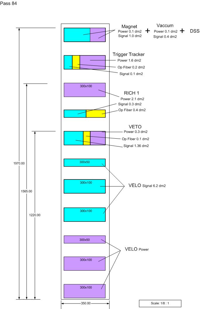
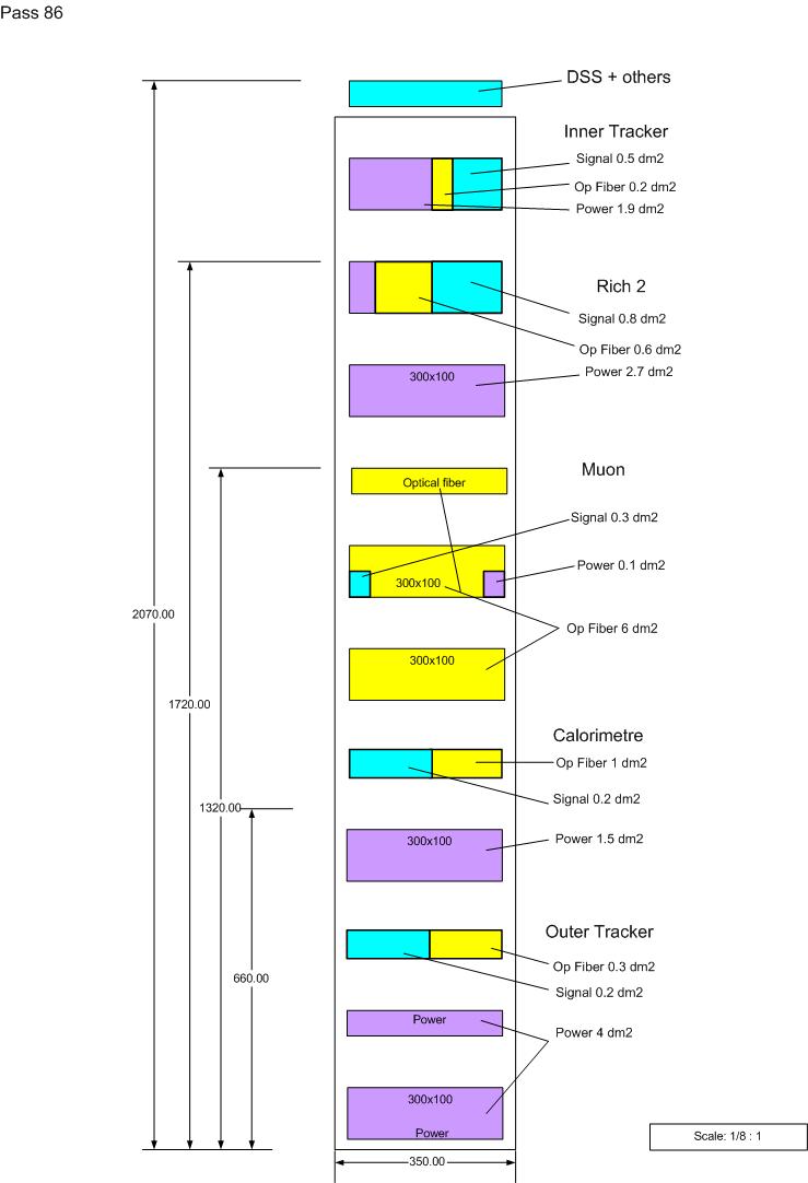
cables" through the chicane is 70 dm2 on each sides (pass 84 and 86). That's 140
dm2 in total.
It will also be the most complicated place to install the cable trays and then
to place the cables into the trays.
A 1/1 scale mock up (model) of the chicane is now available in building 157 to test the disposition of the cable trays and cables (bending radius). All detector groups will be able to test the installation of their cables in the cable trays that have been installed on the chicane mock up.
For the chicane two models of the "Cablofil" cable trays have been choose. They are both 300mm wide with two different heights, 54 and 105 mm, this for an efficiency reason.
Chicane drawing available on EDMS: https://edms.cern.ch/cedar/plsql/doc.info?cookie=2279063&document_id=407101&version=0
Minimum bending radius of the cables
Cable trays disposition
Technical drawings of the chicane will be added soon on this web page. Thank you for your patience.


If you have any comments and/or questions about the site's organization or its content don't hesitate to contact me by e-mail.
| This page was last modified by
VB on
April 19, 2004.This
page has been accessed
|